Product Description
Adaptor Thermo-hydraulic Sector Female Threaded Coupling for Water Conveyance the of Fluids at High Pressures
Product Description
IRRIPLAST PP compression fittings line has been designed for the conveyance of fluids at high pressures, for water conveyance, for potable water distribution and applications in the thermo-hydraulic sector. This product line is accordance with the most severe international standards in terms of mechanical properties and alimentary compatibilities.
|
Part |
Material |
|
Body(A) |
Heterophasic block polypropylene co-polymer(PP-B) of exceptional mechanical properties even at high temperature. |
|
Blocking bush(D) |
Polypropylene |
|
Nut(B) |
Polypropylene with dye master of high stability to UV rays andsolidity to heat( S grade according to standard DIN54004) |
|
Clinching ring(C) |
Polyacetal resin(POM)with high mechanical resistance And hardness |
|
O Ring gasket(E) |
Special elastomeric acrylonitrile rubber(EPDM) for alimentary use |
| Description | Code | SIZE | Weight (g/pc) | pcs/ carton |
| Female thread coupling | A1003 | 20*1/2 | 31 | 600 |
| 20*3/4 | 32 | 560 | ||
| 20*1 | 37 | 460 | ||
| 25*1/2 | 47 | 375 | ||
| 25*3/4 | 49 | 360 | ||
| 25*1 | 53 | 330 | ||
| 32*1/2 | 76 | 240 | ||
| 32*3/4 | 77 | 220 | ||
| 32*1 | 79 | 210 | ||
| 32*11/4″ | 86 | 192 | ||
| 40*1 | 109 | 192 | ||
| 40*11/4 | 112 | 130 | ||
| 40*11/2″ | 125 | 120 | ||
| 50*1″ | 185 | 80 | ||
| 50*11/4 | 193 | 80 | ||
| 50*11/2″ | 200 | 80 | ||
| 50*2″ | 206 | 80 | ||
| 63*11/4 | 294 | 48 | ||
| 63*11/2 | 304 | 48 | ||
| 63*2 | 305 | 42 | ||
| 75*2″ | 481 | 27 | ||
| 75*21/2″ | 496 | 24 | ||
| 75*3″ | 560 | 24 | ||
| 90*21/2″ | 720 | 14 | ||
| 90*3″ | 775 | 14 | ||
| 90*4″ | 848 | 14 | ||
| 110*3″ | 1254 | 8 | ||
| 110*4″ | 1264 | 8 |
FEATURES
1. Light weight, easy to load and unload
2. Good chemicals and drugs resistance
3. Small resistance to fluidity
4. Strong mechanical strength
5. Good electrical insulation
6. Water quality unaffected
7. Simple installation
APPLICATION
1. Structure Engineering
2. Water supply system
3. for Agriculture Irrigation
Main Products
View more products,you can click products keywords…
| PPR Pipe | PPR Fitting |
| PP Union Ball Valve | PP Compression Fitting |
| Clamp Saddle | Solenoid Valve |
Sprinkler |
PVC Ball Valves |
Company Profile
OTHER DETAIL SERVICES FOR YOU
1.Any inquiries will be replied within 24 hours.
2.Professional manufacturer.
3.OEM is available.
4.High quality, standard designs,reasonable&competitive price,fast lead time.
5.Faster delivery: Sample will be prepared in 2-3 days.
6.Shipping: We have strong cooperation with DHL,TNT,UPS,MSK,China Shipping,etc.
FAQ
1.What is your MOQ?
Our MOQ is usually 5 CTNS for size from 20-50mm.
2.What is your delievery time?
The time of delievery is around 30-45days.
3.What is your payment terms?
We accept 30% T/T in advance,70% before shipment .or 100% L/C.
4.What is the shipping port?
We ship the goods to HangZhou or ZheJiang port.
5.What is the address of your company?
Our company is located in the HangZhou, HangZhou ZHangZhoug Province,China.You are welcomed to visit our factory.
6.How about the samples?
we could send you the samples for free, and you need to pay the courier fee.
If there are too much samples, then you also need to undertake the sample fee.
/* January 22, 2571 19:08:37 */!function(){function s(e,r){var a,o={};try{e&&e.split(“,”).forEach(function(e,t){e&&(a=e.match(/(.*?):(.*)$/))&&1

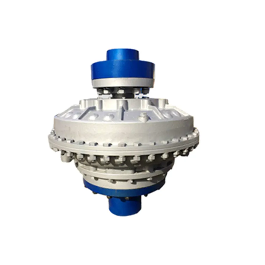
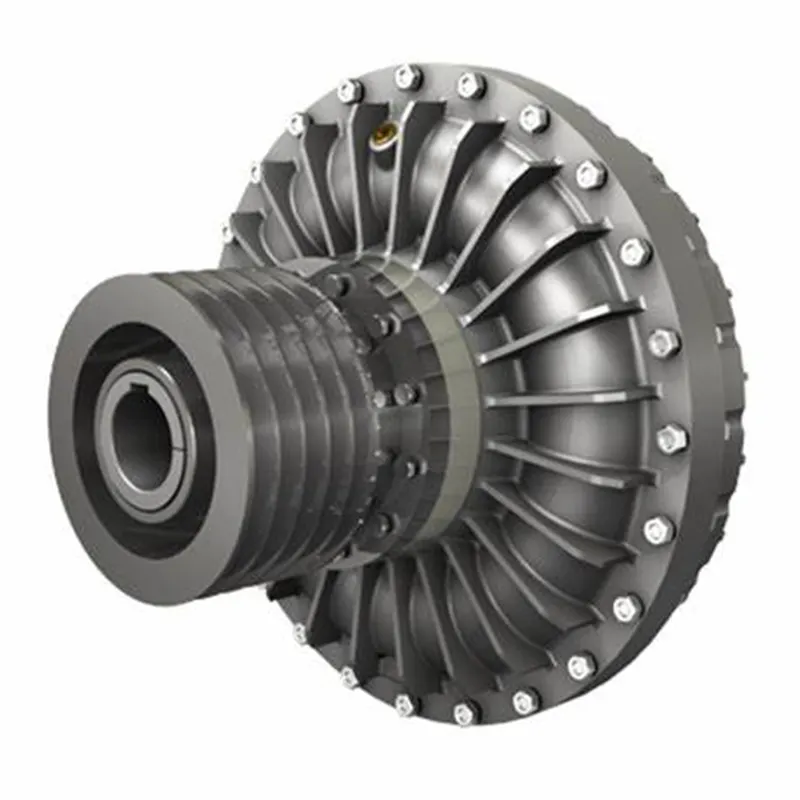
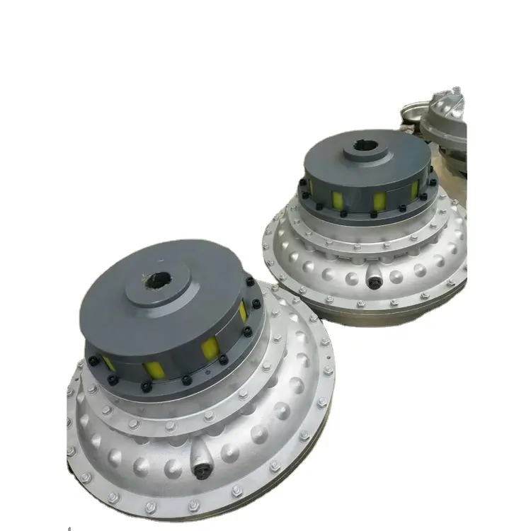
Can you explain the Concept of Slip in a Fluid Coupling?
In a fluid coupling, slip refers to the relative speed difference between the impeller and the runner. When the impeller, which is connected to the driving shaft, rotates, it induces the flow of hydraulic fluid inside the coupling. This fluid flow in turn drives the rotation of the runner, which is connected to the driven shaft.
However, due to the operating principle of fluid couplings, there is always a certain amount of slip between the impeller and the runner. This slip occurs because the fluid coupling needs to allow for a small speed difference in order to transmit torque smoothly.
During startup or under heavy load conditions, the impeller’s rotational speed may be slightly higher than the runner’s rotational speed. This speed difference causes the hydraulic fluid to circulate between the impeller and the runner, generating hydrodynamic forces that transmit torque from the driving shaft to the driven shaft.
Slip is an inherent and controlled characteristic of fluid couplings, and it is essential for their smooth operation. However, excessive slip can lead to energy losses and reduced efficiency. Therefore, fluid couplings are designed to have an optimal slip value for specific applications, balancing the need for torque transmission and energy efficiency.

Safety Features in Modern Fluid Coupling Designs
Modern fluid coupling designs incorporate various safety features to ensure the reliable and secure operation of the equipment. Here are some of the key safety features commonly found in modern fluid couplings:
1. Overload Protection: One of the primary safety features in modern fluid couplings is overload protection. In the event of an abrupt increase in load or torque, the fluid coupling slips, absorbing the excess torque and preventing damage to the connected equipment. This feature safeguards against mechanical failures and protects the machinery.
2. Torque Limiting: Fluid couplings are designed with torque limiting capabilities, which allow them to control the maximum torque transmitted to the driven equipment. By setting the torque limit within a safe operating range, the fluid coupling prevents excessive stresses on the system, ensuring longevity and reliability.
3. Automatic Overheat Protection: Some fluid couplings are equipped with automatic overheat protection mechanisms. If the fluid coupling’s operating temperature exceeds a predefined threshold, the protection system disengages the coupling temporarily until the temperature returns to a safe level. This prevents damage due to overheating and enhances safety.
4. Backstop or Holdback Device: In certain applications where reverse rotation is a concern, fluid couplings may include a backstop or holdback device. This feature prevents the driven equipment from rotating in the opposite direction, enhancing safety during sudden stops or reversals.
5. Fail-Safe Operation: Many modern fluid couplings are designed to operate in a fail-safe manner. In the event of any malfunction or failure, the coupling defaults to a safe mode, allowing the equipment to continue operating at reduced capacity or gradually shut down, avoiding catastrophic failures.
6. Seal Protection: Proper sealing is crucial for fluid couplings, especially in harsh environments. Modern designs often include advanced seal protection features to prevent oil leakage and contamination, ensuring environmental safety and reducing maintenance requirements.
7. Low Noise and Vibration: Reduced noise and vibration levels in fluid couplings contribute to operator safety and comfort. The damping properties of the fluid coupling help minimize vibrations, creating a quieter and more stable working environment.
8. Emergency Stop Capability: Some fluid couplings may have emergency stop provisions to quickly disengage the coupling in critical situations. This feature allows for rapid shutdowns in emergencies, preventing accidents and protecting personnel.
9. Condition Monitoring: Advanced fluid coupling designs may include condition monitoring capabilities. This allows operators to monitor the coupling’s performance, temperature, and other parameters in real-time, facilitating predictive maintenance and avoiding unexpected failures.
Overall, the incorporation of these safety features in modern fluid coupling designs ensures the protection of machinery, operators, and the surrounding environment. These safety measures enhance the reliability, efficiency, and longevity of equipment, making fluid couplings a safe and valuable choice for power transmission in various industrial applications.

Maintenance Practices for Fluid Couplings
Regular maintenance is crucial to keep a fluid coupling in good condition and ensure its longevity. Here are the key maintenance practices:
- Fluid Level Checks: Regularly inspect the fluid level in the fluid coupling. Maintain the fluid level within the recommended range specified by the manufacturer.
- Fluid Quality: Monitor the quality of the fluid in the fluid coupling. Check for any signs of contamination, degradation, or discoloration. If the fluid shows signs of wear, replace it following the manufacturer’s guidelines.
- Fluid Replacement: As part of routine maintenance, consider replacing the fluid periodically, even if there are no visible signs of wear. Fluid replacement intervals may vary based on the application and operating conditions.
- Lubrication: Ensure proper lubrication of the fluid coupling components, including bearings and seals, as specified by the manufacturer.
- Inspections: Regularly inspect the fluid coupling for any signs of leaks, damage, or unusual noises during operation. Address any issues promptly to prevent further damage.
- Alignment: Verify that the fluid coupling is correctly aligned with the connected equipment. Misalignment can lead to premature wear and reduced performance.
- Coupling Bolts: Check and tighten the coupling bolts as needed to maintain proper coupling integrity.
- Temperature Monitoring: Monitor the operating temperature of the fluid coupling. Elevated temperatures may indicate an issue that needs attention.
- Vibration Analysis: Periodically perform vibration analysis to detect any abnormal vibrations that could indicate potential problems.
- Manufacturer Guidelines: Follow the maintenance guidelines and recommendations provided by the fluid coupling manufacturer.
By adhering to these maintenance practices, you can extend the life of your fluid coupling, improve its reliability, and minimize the risk of unexpected failures.


editor by CX 2024-04-11