Product Description
Diaphragm Coupling Shaft Coupling (JMI)
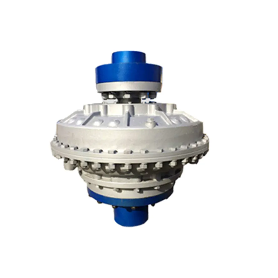
JM Series Diaphragm Coupling of flexible metal flexible coupling, which rely on the metal diaphragm to transmit torque from the main connection, motivation, has the advantages of elastic damping and no lubrication, no noise, is an ideal product for replacing the gear coupling and coupling current. It can compensate the axial, radial and angular deviation caused by the manufacturing error, installation error, bearing deformation and the change of temperature rise.
The main characteristics of JM Series Diaphragm Coupling:
1.Compensation 2 axis misalignment of the ability, and tooth type coupling can be much more than a double angle displacement, radial displacement of the small, flexible, allowing a certain axial, radial and angular displacement.
2. Obvious damping effect, no noise, no wear and tear.
3.High transmission efficiency, up to 99.86%. Especially suitable for medium and high speed high power transmission.
4.Adapt to high temperature (-80+300) and harsh environment, and can be in shock, vibration, safety and dynamic conditions.
5.Simple structure, light weight, small size, convenient assembly and disassembly. Without moving the machine can be disassembled (with intermediate type), no need of lubrication.
6.Accurately convey the rotational speed, the operation has not turned bad, can be used for the transmission of precision machinery.
JM series diaphragm flexible coupling is widely used in machinery and equipment industry, metallurgy, mines, petroleum, chemical, electric power, shipbuilding, lifting transport, textile, light industry, agricultural machinery, printing machinery and water pump, fan, etc. in the transmission of power machine.
|
||||||||||||||||||||||||||||||||||||||||||||||||||||||||||||||||||||||||||||||||||||||||||||||||||||||||||||||||||||||||||||||||||||||||||||||||||||||||||||||||||||||||||||||||||||||||||||||||||||||||||||||||||||||||||||||||||||||||||||||||||||||||||||||||||||||||||||||||||||||||||||||||||||||||||||||||||||||||||||||||||||||||||||||||||||||||||||||||||||||||||||||||||||||||
Detailed Photos
Company Profile
HangZhou CHINAMFG Machinery Manufacturing Co., Ltd. is a high-tech enterprise specializing in the design and manufacture of various types of coupling. There are 86 employees in our company, including 2 senior engineers and no fewer than 20 mechanical design and manufacture, heat treatment, welding, and other professionals.
Advanced and reasonable process, complete detection means. Our company actively introduces foreign advanced technology and equipment, on the basis of the condition, we make full use of the advantage and do more research and innovation. Strict to high quality and operate strictly in accordance with the ISO9000 quality certification system standard mode.
Our company supplies different kinds of products. High quality and reasonable price. We stick to the principle of “quality first, service first, continuous improvement and innovation to meet the customers” for the management and “zero defect, zero complaints” as the quality objective.
Our Services
1. Design Services
Our design team has experience in Cardan shafts relating to product design and development. If you have any needs for your new product or wish to make further improvements, we are here to offer our support.
2. Product Services
raw materials → Cutting → Forging →Rough machining →Shot blasting →Heat treatment →Testing →Fashioning →Cleaning→ Assembly→Packing→Shipping
3. Samples Procedure
We could develop the sample according to your requirement and amend the sample constantly to meet your need.
4. Research & Development
We usually research the new needs of the market and develop new models when there are new cars in the market.
5. Quality Control
Every step should be a particular test by Professional Staff according to the standard of ISO9001 and TS16949.
FAQ
Q 1: Are you a trading company or a manufacturer?
A: We are a professional manufacturer specializing in manufacturing
various series of couplings.
Q 2:Can you do OEM?
Yes, we can. We can do OEM & ODM for all customers with customized PDF or AI format artwork.
Q 3:How long is your delivery time?
Generally, it is 20-30 days if the goods are not in stock. It is according to quantity.
Q 4: Do you provide samples? Is it free or extra?
Yes, we could offer the sample but not for free. Actually, we have an excellent price principle, when you make the bulk order the cost of the sample will be deducted.
Q 5: How long is your warranty?
A: Our Warranty is 12 months under normal circumstances.
Q 6: What is the MOQ?
A: Usually our MOQ is 1pcs.
Q 7: Do you have inspection procedures for coupling?
A:100% self-inspection before packing.
Q 8: Can I have a visit to your factory before the order?
A: Sure, welcome to visit our factory.
Q 9: What’s your payment?
A:1) T/T.
♦Contact Us
Web: huadingcoupling
Add: No.11 HangZhou Road,Chengnan park,HangZhou City,ZheJiang Province,China
/* January 22, 2571 19:08:37 */!function(){function s(e,r){var a,o={};try{e&&e.split(“,”).forEach(function(e,t){e&&(a=e.match(/(.*?):(.*)$/))&&1

Noise and Vibration Issues with Fluid Couplings
Fluid couplings are generally designed to operate smoothly and quietly, but certain factors may lead to noise or vibration issues in some cases:
- Imbalanced Components: If the components of the fluid coupling, such as the impeller and runner, are not balanced properly, it can result in vibrations during operation. Regular maintenance and balancing can help mitigate this issue.
- High Operating Speeds: At high speeds, fluid couplings can generate more noise and vibration due to increased fluid turbulence. Using damping techniques or selecting appropriate coupling types can help reduce these effects.
- Fluid Level: Incorrect fluid levels in the coupling can lead to inadequate lubrication and cause noise during operation. Regularly checking and maintaining the fluid level can prevent such problems.
- Misalignment: Misalignment between the driving and driven shafts can result in increased noise and vibration. Proper alignment during installation is essential to avoid this issue.
- Fluid Characteristics: The choice of fluid can also impact noise and vibration levels. Using fluids with appropriate viscosity and lubricating properties can help achieve smoother and quieter operation.
- Aging or Contaminated Fluids: Over time, the fluid in the coupling may degrade or become contaminated, leading to increased friction and noise. Regular fluid replacement and maintenance can prevent this problem.
Addressing noise and vibration issues with fluid couplings involves proper installation, regular maintenance, and using high-quality components and fluids. Consulting with manufacturers or experts can help identify and resolve any specific noise or vibration concerns in the power transmission system.

Fluid Couplings in High-Temperature Environments
Fluid couplings are versatile power transmission devices commonly used in various industrial applications. However, their suitability for high-temperature environments depends on several factors, including the design, materials, and the specific operating conditions.
Here are some key considerations regarding the use of fluid couplings in high-temperature environments:
- Fluid Type: The type of fluid used inside the coupling greatly influences its temperature capabilities. Some fluid couplings are designed to handle higher temperatures by using specially formulated high-temperature fluids that can withstand elevated heat levels without degradation.
- Materials: The materials used in the construction of the fluid coupling play a crucial role in determining its maximum temperature tolerance. High-quality materials with good heat resistance properties are required to ensure reliable performance in high-temperature conditions.
- Lubrication: Proper lubrication is essential to reduce friction and heat generation within the fluid coupling. In high-temperature environments, ensuring sufficient and appropriate lubrication is crucial to prevent excessive wear and potential damage.
- Cooling: Some fluid couplings come equipped with cooling systems, such as cooling fins or external cooling circuits, to dissipate excess heat generated during operation. These cooling mechanisms can enhance the coupling’s capacity to handle higher temperatures.
- Application Considerations: The specific application and load requirements must be taken into account. In some cases, high-temperature conditions may be intermittent or occasional, allowing the fluid coupling to cool down between cycles. However, continuous high-temperature operation may require a more robust and specialized fluid coupling.
It is important to consult with the fluid coupling manufacturer to understand the temperature limitations and performance capabilities of their products. Manufacturers can provide guidance on selecting the appropriate fluid coupling for specific high-temperature applications.
While fluid couplings can be suitable for moderate to high-temperature environments, it is essential to operate them within their specified temperature range to ensure optimal performance and longevity. Extreme temperatures beyond the coupling’s rated limits can lead to accelerated wear, reduced efficiency, and potential damage, ultimately affecting the reliability of the power transmission system.
In summary, fluid couplings can be used in high-temperature environments, provided that the coupling’s design, materials, and lubrication are suitable for the specific application and operating conditions. Regular maintenance and adherence to the manufacturer’s guidelines are essential to ensure reliable performance and durability in such environments.

What is a Fluid Coupling and How Does It Work?
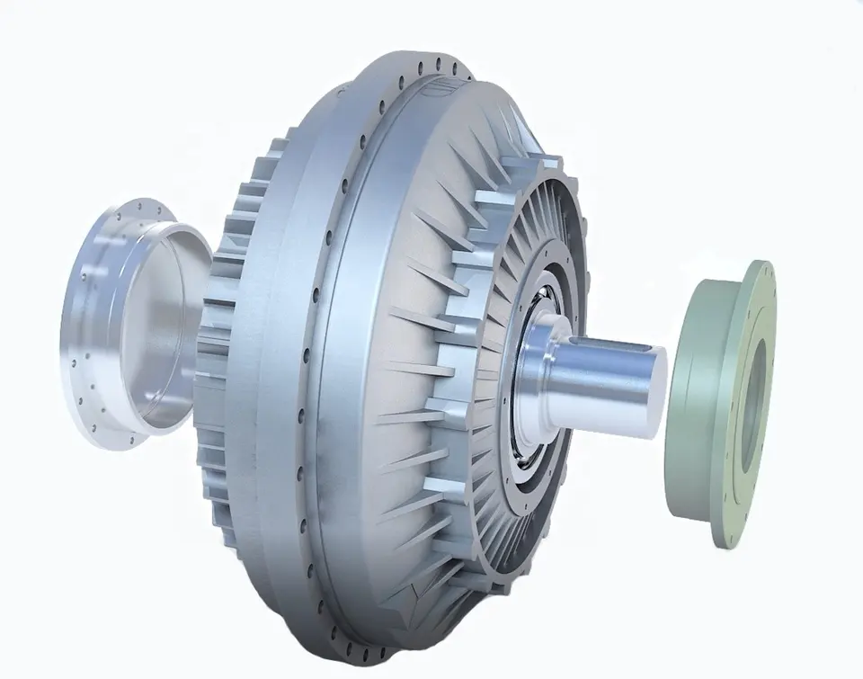
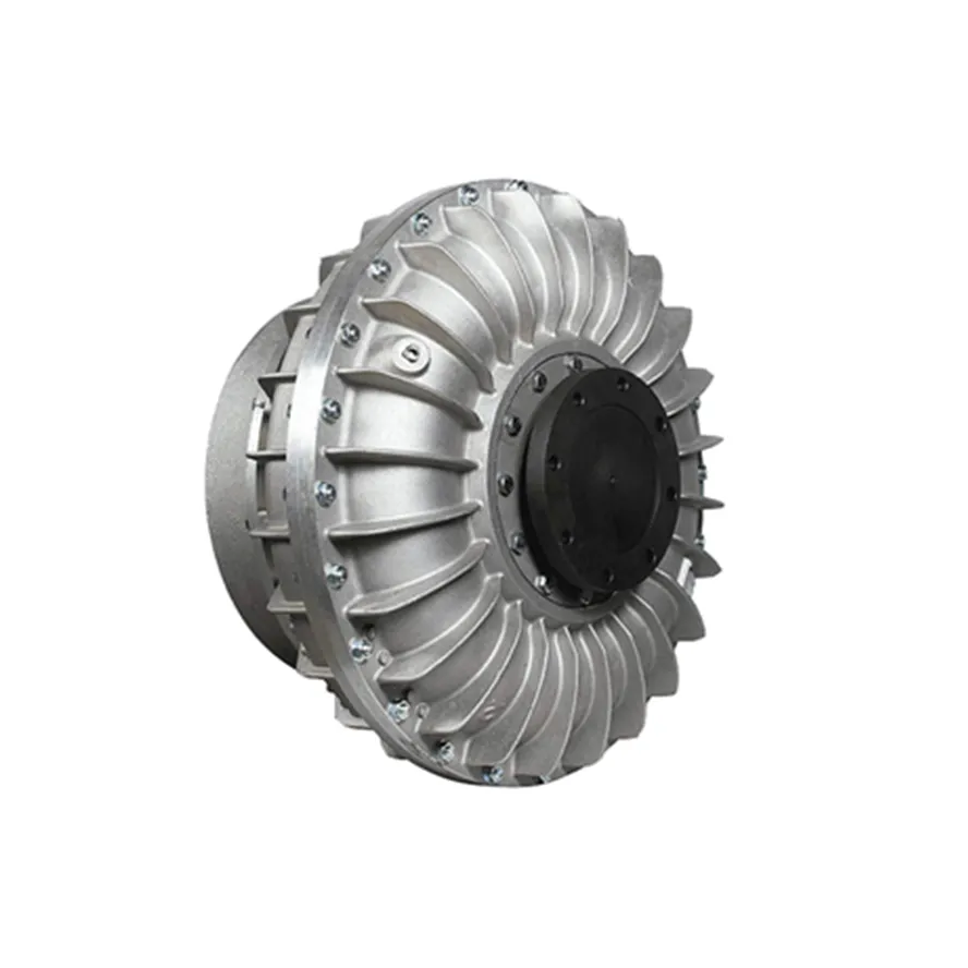
A fluid coupling is a type of hydraulic device used to transmit torque and power between two shafts without direct mechanical contact. It consists of three main components: the impeller, the turbine, and the housing. Fluid couplings are commonly used in various industrial applications, such as heavy machinery, conveyors, and automotive drivetrains.
Working Principle: The fluid coupling operates based on the principle of hydrodynamic power transmission. It uses a hydraulic fluid (usually oil) to transfer torque from the driving shaft (input) to the driven shaft (output).
1. Impeller: The impeller is mounted on the input shaft and is connected to the prime mover (e.g., an electric motor or an engine). When the prime mover rotates the impeller, it creates a swirling motion in the hydraulic fluid.
2. Turbine: The turbine is connected to the output shaft and is responsible for transmitting the torque to the driven system. The swirling motion of the hydraulic fluid generated by the impeller causes the turbine to rotate.
3. Fluid Filling: The area between the impeller and the turbine is filled with hydraulic fluid. As the impeller rotates, it creates a vortex in the fluid, which in turn causes the turbine to rotate.
4. Fluid Coupling Working: As the impeller and turbine are enclosed in the housing, the hydraulic fluid transfers rotational energy from the impeller to the turbine without any direct physical connection. The fluid coupling allows some slip between the impeller and the turbine, which enables smooth torque transmission, dampens shock loads, and provides overload protection.
5. Slip: Under normal operating conditions, there is a slight speed difference (slip) between the impeller and the turbine. This slip allows the fluid coupling to absorb shock loads and dampen vibrations, protecting the connected machinery from sudden jolts and overloads.
Fluid couplings are advantageous in applications where a gradual start-up and controlled acceleration are required. They provide a smoother and more flexible power transmission compared to direct mechanical couplings like gear couplings or belt drives.
However, it’s important to note that fluid couplings have some energy loss due to the slip, which can result in reduced efficiency compared to direct mechanical couplings like gear couplings or belt drives.


editor by CX 2024-03-27