Product Description
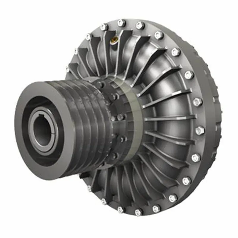
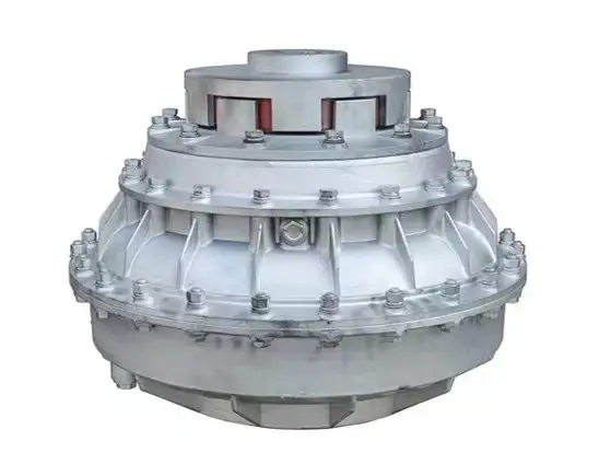
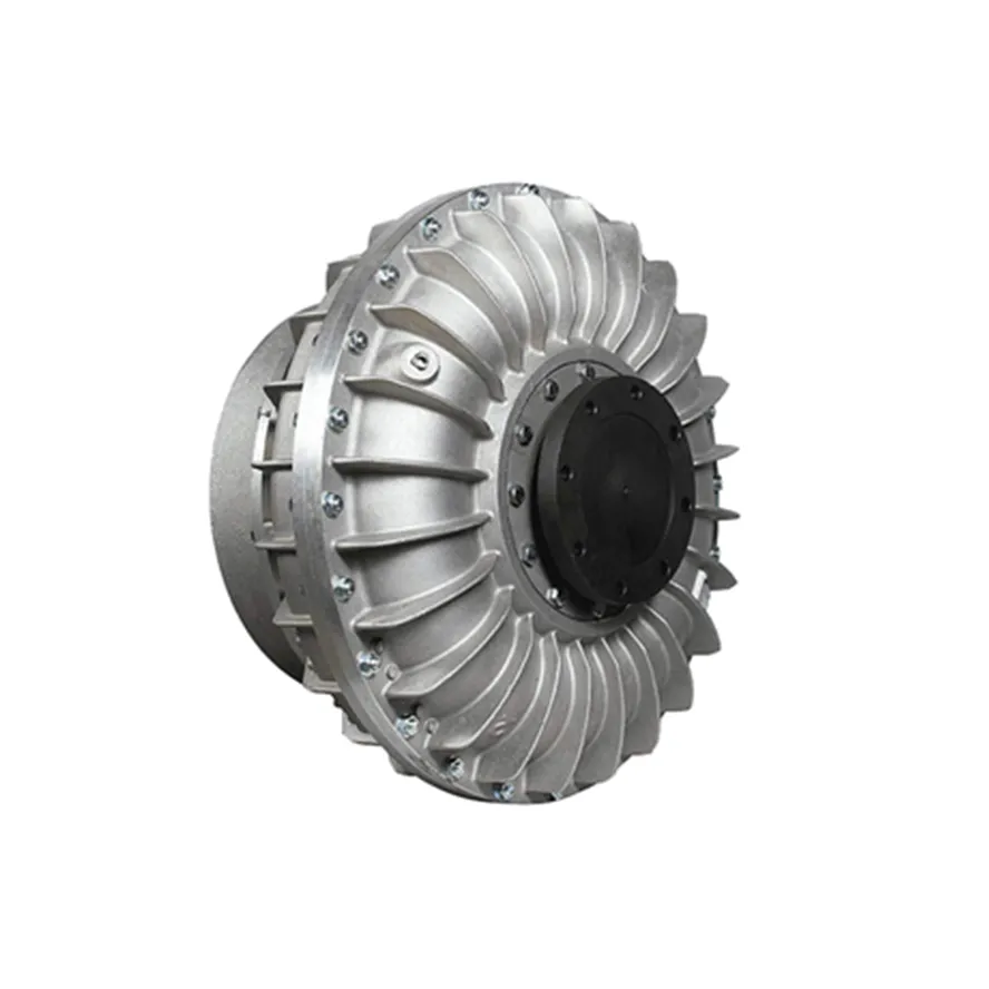
Customized Metal forging hydrodynamic fluid coupling
Muyang machinery is a manufacturer with the capability of comprehensive services of casting, forging and machining, committed to the production of customized parts. Since established in 2002 (former Miaosen Machinery Co., Ltd), we’ve been supplying to the global market for over 15 years, served industries include automotive, railway, gas and oil, medical machinery, construction machinery, gym equipment, etc.
|
Process |
Hot forging, cold forging, die forging with secondary service |
|
Material |
Carbon steel: A36,1045,1035 etc., Alloy steel: 40Cr, 20CrMnTi, 20CrNiMo,42CrMo4 etc., Stainless steel, SS304,SS316 etc. |
|
Standard |
ISO, DIN, ASTM, BS etc. |
|
Weight |
0.1kg – 20kg (in accordance with product structure) |
|
Applicable Machining Process |
CNC Machining/ Lathing/ Milling/ Turning/ Boring/ Drilling/ Tapping/ Broaching/Reaming etc. |
|
Machining Tolerance |
±0.005mm |
|
Machined Surface Quality |
Ra0.8-Ra3.2 according to customer requirement |
|
Applicable Heat Treatment |
Normalization, Quenching and tempering, Case |
|
Hardening, Nitriding, Carbon Nitriding, Induction Quenching |
|
|
Applicable Finish Surface Treatment |
Shot/sand blast, polishing, Surface passivation, Primer Painting , Powder coating, ED- Coating, Chromate Plating, zinc-plate, Dacromat coating, Finish Painting |
|
Testing equipment |
Supersonic inspection machine, Supersonic flaw detecting machine , Physics and chemical analysis etc. |
|
Packing |
Wooden cases or according to customers’ requirement |
|
MOQ of mass production |
1000-5000pcs ( in accordance with actual condition) |
* Part of the warehouse of railway parts
We promise our clients careful, safe and tight package for exporting!
Standard packing: pearl cotton/bubble bag + carton box + pallet/wooden box
Special packing: custom packaging + wooden box
FAQ
1. Are you a manufacturer or trading company?
We’re a manufacturer with self-export rights.
2. What’s your main business?
Our main business is custom metal parts processed by CNC machining, casting, forging etc., serving industries include railway, automobile, construction machinery, gym equipment, water gas and oil.
3. Directly get to CONTACT or send your product drawing/inquiries to email, we will reply within 0.5 hour.
/* March 10, 2571 17:59:20 */!function(){function s(e,r){var a,o={};try{e&&e.split(“,”).forEach(function(e,t){e&&(a=e.match(/(.*?):(.*)$/))&&1

Fluid Couplings in Conjunction with Electric Motors
Yes, fluid couplings can be used in conjunction with electric motors to provide a reliable and efficient power transmission solution. When coupled with an electric motor, the fluid coupling serves as a mechanical torque converter, enabling smooth start-ups and gradual acceleration of the driven load.
The combination of a fluid coupling and an electric motor offers several advantages:
- Soft Start: When the electric motor is switched on, it accelerates gradually as the fluid coupling allows the torque to build up slowly. This soft start feature reduces mechanical stress on the driven equipment and minimizes the impact on the electrical supply, preventing voltage drops and surges.
- Overload Protection: Fluid couplings can automatically disengage when the load exceeds a certain threshold, providing overload protection to both the motor and the driven equipment. This feature helps prevent damage to the system during abrupt load changes or stall conditions.
- Vibration Damping: The fluid in the coupling acts as a damping medium, reducing vibration and shock loads during start-ups and sudden load changes. This contributes to smoother operation and extends the lifespan of the connected machinery.
- Energy Efficiency: By facilitating soft start and controlling torque transmission, fluid couplings improve the energy efficiency of the system. They reduce the inrush current during start-up, which can lead to significant energy savings in the long run.
- Variable Speed Control: In some configurations, fluid couplings can be combined with Variable Frequency Drives (VFDs) to provide variable speed control. The VFD regulates the speed of the electric motor, while the fluid coupling ensures smooth and controlled power transmission to the driven equipment.
Overall, the combination of a fluid coupling with an electric motor is a versatile solution that finds applications in various industries. It allows for reliable and controlled power transmission, protecting both the motor and the driven equipment while improving system efficiency.

Real-World Case Studies: Improved Performance with Fluid Couplings
Fluid couplings have been widely adopted in various industries, and numerous real-world case studies demonstrate their positive impact on performance and efficiency. Here are a few examples:
Case Study 1: Mining Conveyor System
In a large mining operation, a conveyor system used to transport heavy loads of ore experienced frequent starts and stops due to fluctuating material supply. The abrupt starting and stopping led to significant wear and tear on the conveyor components, causing frequent breakdowns and maintenance downtime.
After installing fluid couplings at critical points in the conveyor system, the soft start and stop capability of the fluid couplings significantly reduced the mechanical stress during operation. This led to a smoother material flow, reduced conveyor wear, and extended equipment life. Additionally, the fluid couplings’ overload protection feature prevented damage to the conveyor during peak loads, ensuring uninterrupted production.
Case Study 2: Marine Propulsion System
In a marine vessel equipped with traditional direct drive systems, the crew faced challenges in maneuvering the ship efficiently. The fixed propeller arrangement made it challenging to control the vessel’s speed and direction accurately, leading to increased fuel consumption and decreased maneuverability.
By retrofitting the vessel’s propulsion system with fluid couplings, the ship’s performance improved significantly. The fluid couplings allowed for flexible and smooth speed control, enabling precise maneuvering and reduced fuel consumption. The ability to adjust the load on the propeller enhanced the vessel’s overall efficiency, resulting in reduced operating costs and improved environmental sustainability.
Case Study 3: Industrial Pumping Station
In an industrial pumping station, the constant starting and stopping of the pumps caused water hammer and pressure surges within the pipeline network. The sudden hydraulic shocks led to pipe bursts, valve failures, and increased energy consumption.
After implementing fluid couplings in the pump drive systems, the pumps could be softly started and stopped. The fluid couplings’ torque control capabilities ensured a gradual increase in pump speed, eliminating water hammer and pressure surges. As a result, the pumping station’s reliability improved, maintenance costs decreased, and the energy consumption reduced due to smoother pump operations.
These case studies demonstrate the positive effects of using fluid couplings in various applications. They highlight how fluid couplings contribute to improved performance, reduced mechanical stress, enhanced control, and cost savings in industrial machinery and systems.
“`
What is a Fluid Coupling and How Does It Work?
A fluid coupling is a type of hydraulic device used to transmit torque and power between two shafts without direct mechanical contact. It consists of three main components: the impeller, the turbine, and the housing. Fluid couplings are commonly used in various industrial applications, such as heavy machinery, conveyors, and automotive drivetrains.
Working Principle: The fluid coupling operates based on the principle of hydrodynamic power transmission. It uses a hydraulic fluid (usually oil) to transfer torque from the driving shaft (input) to the driven shaft (output).
1. Impeller: The impeller is mounted on the input shaft and is connected to the prime mover (e.g., an electric motor or an engine). When the prime mover rotates the impeller, it creates a swirling motion in the hydraulic fluid.
2. Turbine: The turbine is connected to the output shaft and is responsible for transmitting the torque to the driven system. The swirling motion of the hydraulic fluid generated by the impeller causes the turbine to rotate.
3. Fluid Filling: The area between the impeller and the turbine is filled with hydraulic fluid. As the impeller rotates, it creates a vortex in the fluid, which in turn causes the turbine to rotate.
4. Fluid Coupling Working: As the impeller and turbine are enclosed in the housing, the hydraulic fluid transfers rotational energy from the impeller to the turbine without any direct physical connection. The fluid coupling allows some slip between the impeller and the turbine, which enables smooth torque transmission, dampens shock loads, and provides overload protection.
5. Slip: Under normal operating conditions, there is a slight speed difference (slip) between the impeller and the turbine. This slip allows the fluid coupling to absorb shock loads and dampen vibrations, protecting the connected machinery from sudden jolts and overloads.
Fluid couplings are advantageous in applications where a gradual start-up and controlled acceleration are required. They provide a smoother and more flexible power transmission compared to direct mechanical couplings like gear couplings or belt drives.
However, it’s important to note that fluid couplings have some energy loss due to the slip, which can result in reduced efficiency compared to direct mechanical couplings like gear couplings or belt drives.


editor by CX 2024-01-15